
Question 1
A potential divider consists of a battery of e.m.f. 6.00 V and negligible internal resistance connected in series with a resistor of resistance 120 Ω and a variable resistor of resistance 0 → 200 Ω. Determine the range of potential difference that can be obtained across the fixed resistor.
Easy
Mark as Complete
Mark Scheme
Question 2
A battery of electromotive force (e.m.f.) 9.0 V and internal resistance 1.0 Ω is connected to a fixed resistor of resistance 5.0 Ω and a potentiometer of maximum resistance 3.0 Ω, as shown.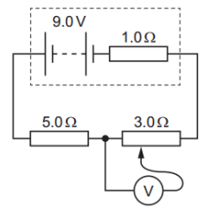 The sliding contact of the potentiometer is moved over its full range of movement.
What is the maximum value of the potential difference that is measured by the voltmeter?
A. 3.0 V.
B. 3.4 V.
C. 4.5 V.
D. 5.4 V.
Medium
Mark as Complete
Mark Scheme
Question 3
A battery of e.m.f. 6.0V and negligible internal resistance is connected to a network of resistors and a voltmeter, as shown in figure. Resistor Y has a resistance of 24 Ω and resistor Z has a resistance of 32 Ω.
The resistance RX of the variable resistor X is adjusted until the voltmeter reads 4.8 V. Calculate:
a. The current in resistor Z.
b. The total power provided by the battery.
c. The number of conduction electrons that move through the battery in a time interval of 25 s.
d. The total resistance of X and Y connected in parallel.
e. The resistance RX.
Medium
Mark as Complete
Mark Scheme
Question 4
Potential differences across two resistors of resistances R1 and R2 are compared using a potentiometer wire (uniform resistance wire) in the electrical circuit shown.
One terminal of a galvanometer is connected to point X. The galvanometer reads zero when its
other terminal is connected to a point that is a distance of 60 cm from one end of the
potentiometer wire.
One terminal of a second galvanometer is connected to point Y. This galvanometer reads zero
when its other terminal is connected to a point that is a distance of 80 cm from the same end of
the potentiometer wire.
What is the ratio `R_2/R_1` ?
Medium
Mark as Complete
Mark Scheme
Question 5
A circuit consists of a battery, a high-resistance voltmeter and four fixed resistors, as shown. The battery has an electromotive force (e.m.f.) of 15.0 V and negligible internal resistance. What is the reading on the voltmeter?
Medium
Mark as Complete
Mark Scheme
Question 6
Three batteries and three identical resistors are connected in a circuit PQR, as shown.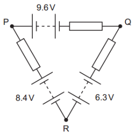 The batteries have negligible internal resistance.
What is the potential difference between points P and Q?
A. 1.5 V.
B. 2.1 V.
C. 7.1 V.
D. 12.1 V.
Medium
Mark as Complete
Mark Scheme
Question 7
In the circuit shown, the 6.0 V battery has negligible internal resistance. Resistors R1 and R2 and the voltmeter each have a resistance of 100 kΩ.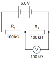 What is the current in the resistor R2?
A. 20 μA.
B. 30 μA.
C. 40 μA.
D. 60 μA.
Medium
Mark as Complete
Mark Scheme
Question 8
A potential divider consists of two resistors of resistances R1 and R2 connected in series across a source of potential difference (p.d.) Vin. The p.d. across R1 is Vout.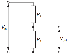 Which changes to R1 and R2 will increase the value of Vout?
| R1 | R2 | |
|---|---|---|
| A | doubled | doubled |
| B | doubled | halved |
| C | halved | doubled |
| D | halved | halved |
Medium
Mark as Complete
Mark Scheme
Question 9
A power supply and a solar cell are compared using the potentiometer circuit shown. The potentiometer wire PQ is 100.0 cm long and has a resistance of 5.00 Ω. The power supply has an e.m.f. of 2.000 V and the solar cell has an e.m.f. of 5.00 mV.
Which resistance R must be used so that the galvanometer reads zero when PS = 40.0 cm?
A. 395 Ω.
B. 405 Ω.
C. 795 Ω.
D. 805 Ω.
Medium
Mark as Complete
Mark Scheme
Question 10
A potential divider circuit is designed to detect the difference in temperature between two different places. The cell has electromotive force (e.m.f.) 20 mV and negligible internal resistance.
Initially, thermistors X and Y are at the same temperature and have the same resistance. The voltmeter reads 10 mV. X is then placed in a cold environment and its resistance doubles. Y is placed in a warm environment and its resistance halves.
What is the new reading on the voltmeter?
Hard
Mark as Complete
Mark Scheme
Question 1
A potential divider consists of a battery of e.m.f. 6.00 V and negligible internal resistance connected in series with a resistor of resistance 120 Ω and a variable resistor of resistance 0 → 200 Ω. Determine the range of potential difference that can be obtained across the fixed resistor.
When the variable resistor is at 0Ω: `V = (120 / (120 + 0)) xx6 = "6 V"`
When the variable resistor is at 200Ω: `V = (120 / (120 + 200)) xx 6 = (120 / 320) xx 6 = "2.25 V"`
The range is 2.25 V → 6.00 V
Question 2
A battery of electromotive force (e.m.f.) 9.0 V and internal resistance 1.0 Ω is connected to a fixed resistor of resistance 5.0 Ω and a potentiometer of maximum resistance 3.0 Ω, as shown.The sliding contact of the potentiometer is moved over its full range of movement.
What is the maximum value of the potential difference that is measured by the voltmeter?
A. 3.0 V.
B. 3.4 V.
C. 4.5 V.
D. 5.4 V.
Answer: A
Voltmeter measures the voltage across the potentiometer, which varies from 0 V to the maximum voltage drop across it.
Total resistance in the circuit (when potentiometer at max resistance):
`R_("total") =r+R+R_("pot")= 1 + 5 + 3 = 9 " " Omega`
Total current in the circuit: `I = E / R_("total") = 9 / 9 = "1 A"`
Voltage drop across the potentiometer (maximum case):
`V_("pot") = I xx R_("pot") = 1 xx 3 = "3 V"`
Question 3
A battery of e.m.f. 6.0V and negligible internal resistance is connected to a network of resistors and a voltmeter, as shown in figure. Resistor Y has a resistance of 24 Ω and resistor Z has a resistance of 32 Ω.
The resistance RX of the variable resistor X is adjusted until the voltmeter reads 4.8 V. Calculate:
a. The current in resistor Z.
b. The total power provided by the battery.
c. The number of conduction electrons that move through the battery in a time interval of 25 s.
d. The total resistance of X and Y connected in parallel.
e. The resistance RX.
a. `I_Z = 4.8 / 32 = "0.15 A"`
b. `P = VxxI= 6 xx 0.15 = "0.90 W"`
c. Total charge: `Q = Ixxt= 0.15 xx 25 = "3.75 C"`
Each electron carries e = 1.6×10⁻¹⁹ C, so number of electrons:
`n =Q/e= 3.75 / (1.6 xx 10^-19) ≈ 2.34 xx 10^19`
d. The remaining voltage drop after Z: `V _("XY") =6.0−4.8="1.2 V"`
Total resistance of X‖Y: `R_("XY") = 1.2 / 0.15 = 8 " " Omega`
e. RY = 24 Ω.
Total parallel resistance RP = 8 Ω.
`1/R_P = 1/R_X + 1/24 => 1/8 = 1/R_X + 1/24 => R_X = 12 " " Omega`
Question 4
Potential differences across two resistors of resistances R1 and R2 are compared using a potentiometer wire (uniform resistance wire) in the electrical circuit shown.
One terminal of a galvanometer is connected to point X. The galvanometer reads zero when its
other terminal is connected to a point that is a distance of 60 cm from one end of the
potentiometer wire.
One terminal of a second galvanometer is connected to point Y. This galvanometer reads zero
when its other terminal is connected to a point that is a distance of 80 cm from the same end of
the potentiometer wire.
What is the ratio `R_2/R_1` ?
corresponds to 80 cm from the same end, so the length representing only R2:
80 cm − 60 cm = 20 cm.
Hence, V1 ∝ 60 and V2 ∝ 20.
Since both resistors are connected in series with the same current I:
`V_1 = I xx R_1, " " V_2 = I xx R_2 => V_2 / V_1 = R_2 / R_1`
`R_2 / R_1 = V_2 / V_1 = 20 / 60 = 1 / 3`
Question 5
A circuit consists of a battery, a high-resistance voltmeter and four fixed resistors, as shown. The battery has an electromotive force (e.m.f.) of 15.0 V and negligible internal resistance.What is the reading on the voltmeter?
Left side: 24 Ω (top) and 6 Ω (bottom)
Voltage at the midpoint (between 24 Ω and 6 Ω), relative to the bottom (0 V):
`V_("left") = (6 / (24 + 6)) xx 15 = (6 / 30) xx 15 = "3 V"`
Right side: 6 Ω (top) and 9 Ω (bottom)
Voltage at the midpoint:
`V_("right") = (9 / (6 + 9)) xx 15 = (9 / 15) xx 15 = 9 V`
Voltage across the voltmeter (difference between midpoints):
`V = V_("right") - V_("left") = 9 - 3 = "6 V"`
Question 6
Three batteries and three identical resistors are connected in a circuit PQR, as shown.The batteries have negligible internal resistance.
What is the potential difference between points P and Q?
A. 1.5 V.
B. 2.1 V.
C. 7.1 V.
D. 12.1 V.
Answer: B
Let’s the potential at point R is zero.
Moving from R to P through the 8.4 V battery and resistor:
Voltage at point P: `V_P = 8.4 - IxxR`
Moving from R to Q through the 6.3 V battery and resistor:
Voltage at point Q: `V_Q = 6.3 - IxxR`
Find VP − : `V_P - V_Q = (8.4 - IxxR) - (6.3 - IxxR) = "2.1 V"`
Question 7
In the circuit shown, the 6.0 V battery has negligible internal resistance. Resistors R1 and R2 and the voltmeter each have a resistance of 100 kΩ.What is the current in the resistor R2?
A. 20 μA.
B. 30 μA.
C. 40 μA.
D. 60 μA.
Answer: C
Since both R2 and the voltmeter are 100 kΩ and are in parallel, the equivalent resistance:
`R_("eq") = 1 / (1/100000 + 1/100000) = 50000 " " Omega`
Total circuit resistance: `R_("total") = R_1+R_("eq")= 100000 + 50000 = 150000 " " Omega`
Total current from the battery: `I_("total") = V/R= 6 / 150000 = 40 " " mu"A"`
Current through R2: `I_(R_2) =I_("total")/2 = 40 / 2 = 20 " " mu"A"`
Question 8
A potential divider consists of two resistors of resistances R1 and R2 connected in series across a source of potential difference (p.d.) Vin. The p.d. across R1 is Vout.Which changes to R1 and R2 will increase the value of Vout?
| R1 | R2 | |
|---|---|---|
| A | doubled | doubled |
| B | doubled | halved |
| C | halved | doubled |
| D | halved | halved |
Answer: B
The formula for the output voltage across R1: `V_"out" = (R_1 / (R_1 + R_2)) xx V_"in"`
To increase Vout, we need the fraction `(R_1 / (R_1 + R_2))` to increase.
That happens when: increases (numerator increases) and/or R2 decreases (denominator decreases).
A. Correct: `V_"out" = (2R_1) / (2R_1 + 2R_2) = R_1 / (R_1 + R_2)`
No change to the voltage ratio.
B. Correct:
is doubled → increases numerator.
R2 is halved → decreases denominator.
Fraction increases ⇒ Vout increases.
C. Incorrect: Numerator decreases, denominator increases ⇒ Vout decreases.
D. Incorrect: `V_"out" = (0.5R_1) / (0.5R_1 + 0.5R_2) = R_1 / (R_1 + R_2)`
No change to the voltage ratio.
Question 9
A power supply and a solar cell are compared using the potentiometer circuit shown.The potentiometer wire PQ is 100.0 cm long and has a resistance of 5.00 Ω. The power supply has an e.m.f. of 2.000 V and the solar cell has an e.m.f. of 5.00 mV.
Which resistance R must be used so that the galvanometer reads zero when PS = 40.0 cm?
A. 395 Ω.
B. 405 Ω.
C. 795 Ω.
D. 805 Ω.
Answer: C
Total resistance in the circuit: R + 5.00 Ω
Current from the 2.000 V power supply: `I = 2.000 / (R + 5)`
Voltage per cm: `Ixx5.00/100=Ixx0.05`
So, voltage across 40.0 cm: `V_("PS") = I xx (40.00xx0.05) = I xx 2.0`
`V_("PS") = (2 / (R + 5)) xx2 = 4 / (R + 5)`
At null point (galvanometer reads zero), this voltage must equal the solar cell e.m.f:
`4 / (R + 5) = 0.005`
`R = 800 - 5 = 795 " "Omega`
Question 10
A potential divider circuit is designed to detect the difference in temperature between two different places.The cell has electromotive force (e.m.f.) 20 mV and negligible internal resistance.
Initially, thermistors X and Y are at the same temperature and have the same resistance. The voltmeter reads 10 mV. X is then placed in a cold environment and its resistance doubles. Y is placed in a warm environment and its resistance halves.
What is the new reading on the voltmeter?
Answer: A
Initially:
RX = R
RY = RTotal resistance = R + R = 2R
Using voltage division rule: `V = (R / (R + R)) xx 20 = (1/2) xx 20 = "10 mV"`
After temperature change:
RX = 2R
RY = R/2
Total resistance = 2R + R/2 = 5R/2
New voltmeter reading:
Question 1
A potential divider consists of a battery of e.m.f. 6.00 V and negligible internal resistance connected in series with a resistor of resistance 120 Ω and a variable resistor of resistance 0 → 200 Ω. Determine the range of potential difference that can be obtained across the fixed resistor.
Question 2
A battery of electromotive force (e.m.f.) 9.0 V and internal resistance 1.0 Ω is connected to a fixed resistor of resistance 5.0 Ω and a potentiometer of maximum resistance 3.0 Ω, as shown.The sliding contact of the potentiometer is moved over its full range of movement.
What is the maximum value of the potential difference that is measured by the voltmeter?
A. 3.0 V.
B. 3.4 V.
C. 4.5 V.
D. 5.4 V.
Question 3
A battery of e.m.f. 6.0V and negligible internal resistance is connected to a network of resistors and a voltmeter, as shown in figure. Resistor Y has a resistance of 24 Ω and resistor Z has a resistance of 32 Ω.
The resistance RX of the variable resistor X is adjusted until the voltmeter reads 4.8 V. Calculate:
a. The current in resistor Z.
b. The total power provided by the battery.
c. The number of conduction electrons that move through the battery in a time interval of 25 s.
d. The total resistance of X and Y connected in parallel.
e. The resistance RX.
Question 4
Potential differences across two resistors of resistances R1 and R2 are compared using a potentiometer wire (uniform resistance wire) in the electrical circuit shown.
One terminal of a galvanometer is connected to point X. The galvanometer reads zero when its
other terminal is connected to a point that is a distance of 60 cm from one end of the
potentiometer wire.
One terminal of a second galvanometer is connected to point Y. This galvanometer reads zero
when its other terminal is connected to a point that is a distance of 80 cm from the same end of
the potentiometer wire.
What is the ratio `R_2/R_1` ?
Question 5
A circuit consists of a battery, a high-resistance voltmeter and four fixed resistors, as shown. The battery has an electromotive force (e.m.f.) of 15.0 V and negligible internal resistance.What is the reading on the voltmeter?
Question 6
Three batteries and three identical resistors are connected in a circuit PQR, as shown.The batteries have negligible internal resistance.
What is the potential difference between points P and Q?
A. 1.5 V.
B. 2.1 V.
C. 7.1 V.
D. 12.1 V.
Question 7
In the circuit shown, the 6.0 V battery has negligible internal resistance. Resistors R1 and R2 and the voltmeter each have a resistance of 100 kΩ.What is the current in the resistor R2?
A. 20 μA.
B. 30 μA.
C. 40 μA.
D. 60 μA.
Question 8
A potential divider consists of two resistors of resistances R1 and R2 connected in series across a source of potential difference (p.d.) Vin. The p.d. across R1 is Vout.Which changes to R1 and R2 will increase the value of Vout?
| R1 | R2 | |
|---|---|---|
| A | doubled | doubled |
| B | doubled | halved |
| C | halved | doubled |
| D | halved | halved |
Question 9
A power supply and a solar cell are compared using the potentiometer circuit shown.The potentiometer wire PQ is 100.0 cm long and has a resistance of 5.00 Ω. The power supply has an e.m.f. of 2.000 V and the solar cell has an e.m.f. of 5.00 mV.
Which resistance R must be used so that the galvanometer reads zero when PS = 40.0 cm?
A. 395 Ω.
B. 405 Ω.
C. 795 Ω.
D. 805 Ω.
Question 10
A potential divider circuit is designed to detect the difference in temperature between two different places.The cell has electromotive force (e.m.f.) 20 mV and negligible internal resistance.
Initially, thermistors X and Y are at the same temperature and have the same resistance. The voltmeter reads 10 mV. X is then placed in a cold environment and its resistance doubles. Y is placed in a warm environment and its resistance halves.
What is the new reading on the voltmeter?

